Retour de Super Heavy - Projet d'étude
Par DAVID Lucas
Dernière mise à jour: 16 Septembre 2025
Language
Description
La robotique étant un domaine très large, j'ai proposé en projet d'étude un sujet d'aérospatiale avec une approche robotique, qui fait intervenir passion, théorie, et pratique.
Mon sujet a été accepté par M.FOFI, mon professeur encadrant, en une vingtaine de minutes.
L'objectif est de rétro-concevoir la commande du retour d'un propulseur de fusée, Super Heavy.
Le propulseur passe par plusieurs phases lors de sa descente, avec des moyens de guidances différents dans un environnement perturbé (aérodynamiquement, erreurs de commandes et autres).
Une chose aussi compliquée à expliquer bloquée derrière un écran d'ordinateur est plus que dommage, et empêche de vulgariser la science au grand public, c'est une des raisons de pourquoi je veux reproduire ma simulation à échelle humaine dans une cellule robotisée.
Et enfin, utiliser cette reproduction physique pour mettre en place une simulation "hardware-in-the-loop", où j'utilise la lecture de vrais capteurs montés sur mes maquettes, pour alimenter ma simulation.
Les différentes étapes incluent :
- Descente (guidance à l'aide des grilles aérodynamiques)
- Freinage (allumage de ~13 moteurs)
- Dernière manoeuvre (retour de Super Heavy sur les bras de la tour avec 3 moteurs)
Mon étude commence à 40km d'altitude, avant que l'atmosphère ne soit assez dense pour avoir une influance sur la trajectoire du propulseur.
Actuellement, ma principale occupation est de m'assurer que mon projet est faisable, je m'occupe donc de faire fonctionner et coordonner toutes les parties du projet : un proof-of-concept. Je m'appuierais à la précision et aux très fins détails une fois tout cadencé.
Essai n°5 Starship/Super Heavy, par SpaceX
Le propulseur exécute une rentrée atmosphérique et fait une dernière manoeuvre, moteurs allumés, pour se faire attraper
Simulation
J'utilise MuJoCo, en C++, car c'est un moteur physique très utilisé aujourd'hui pour la recherche et des application d'apprentissage par renforcement, notamment chez Nvidia ou Google Deepmind.
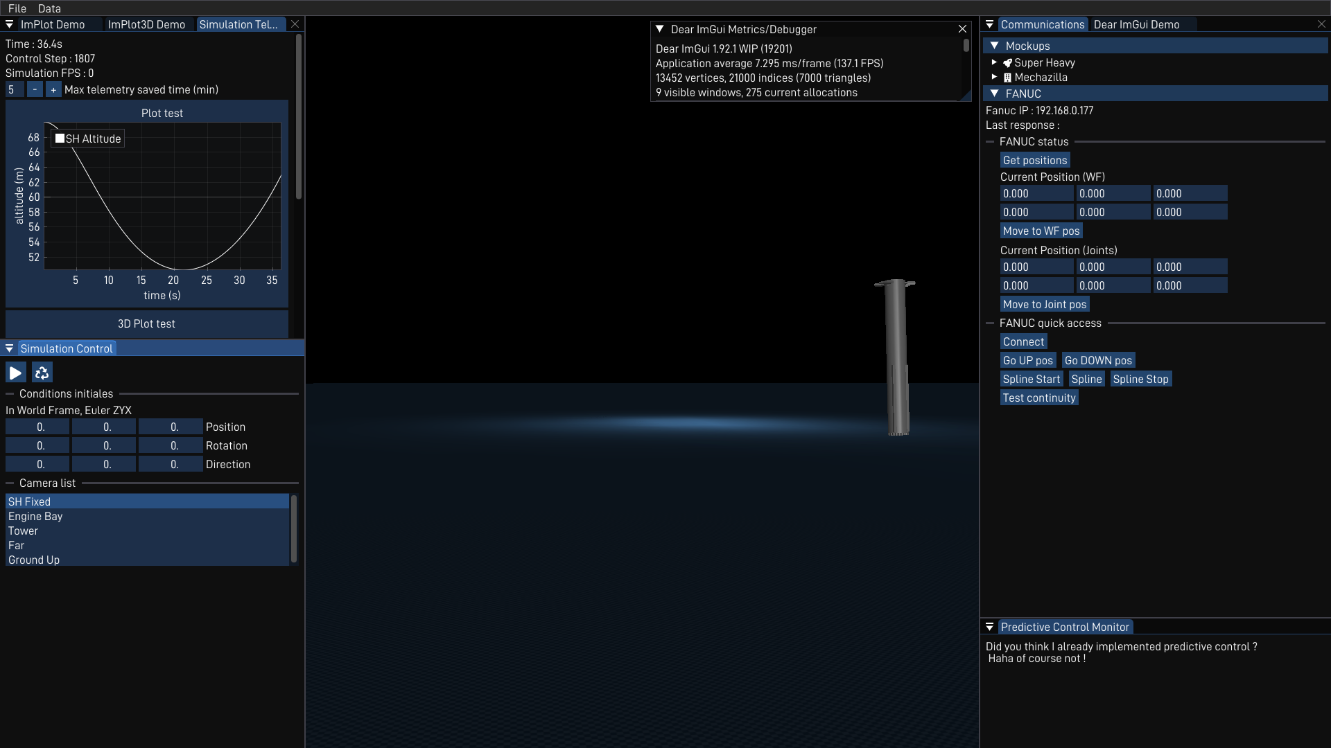
ProxSim, logiciel de simulation/contrôle à distance.
Interface en développement
Voici mon environnement de simulation, avec un modèle simpliste de Super Heavy. J'ai implémenté l'export de données en CSV, mon contrôleur de vol, et une interface pour interagir avec la simulation et avec les autres composants de mon projet (maquettes, cellule robotisée FANUC).
Super Heavy pour l'instant se tient "droit"/"debout" en tournant ses moteurs (guidance par TVC, Thrust Vector Control), peu importe sa position de départ, à l'aide de simples PIDs. Cet objectif fût surtout un bon prétexte pour mettre en place une simulation contrôlée, stable et réaliste.
On peux voir au centre de l'écran, l'environnement de simulation MuJoCo, avec le propulseur. Et sur le reste de l'écran, une interface ImGui me permet de mettre en pause, relancer la simulation, modifier la caméra, modifier mes conditions initiales et relever la télémétrie importante comme l'altitude du propulseur, son accélération ou l'état de ses moteurs.
Je peux aussi depuis cette interface contrôler la cellule robotisée FANUC, autant pour envoyer des commandes manuelles simples de mouvement, ou des suivis de trajectoires complexes (c.f. partie Contrôle de la cellule robotisée).
Contrôle de la cellule robotisée
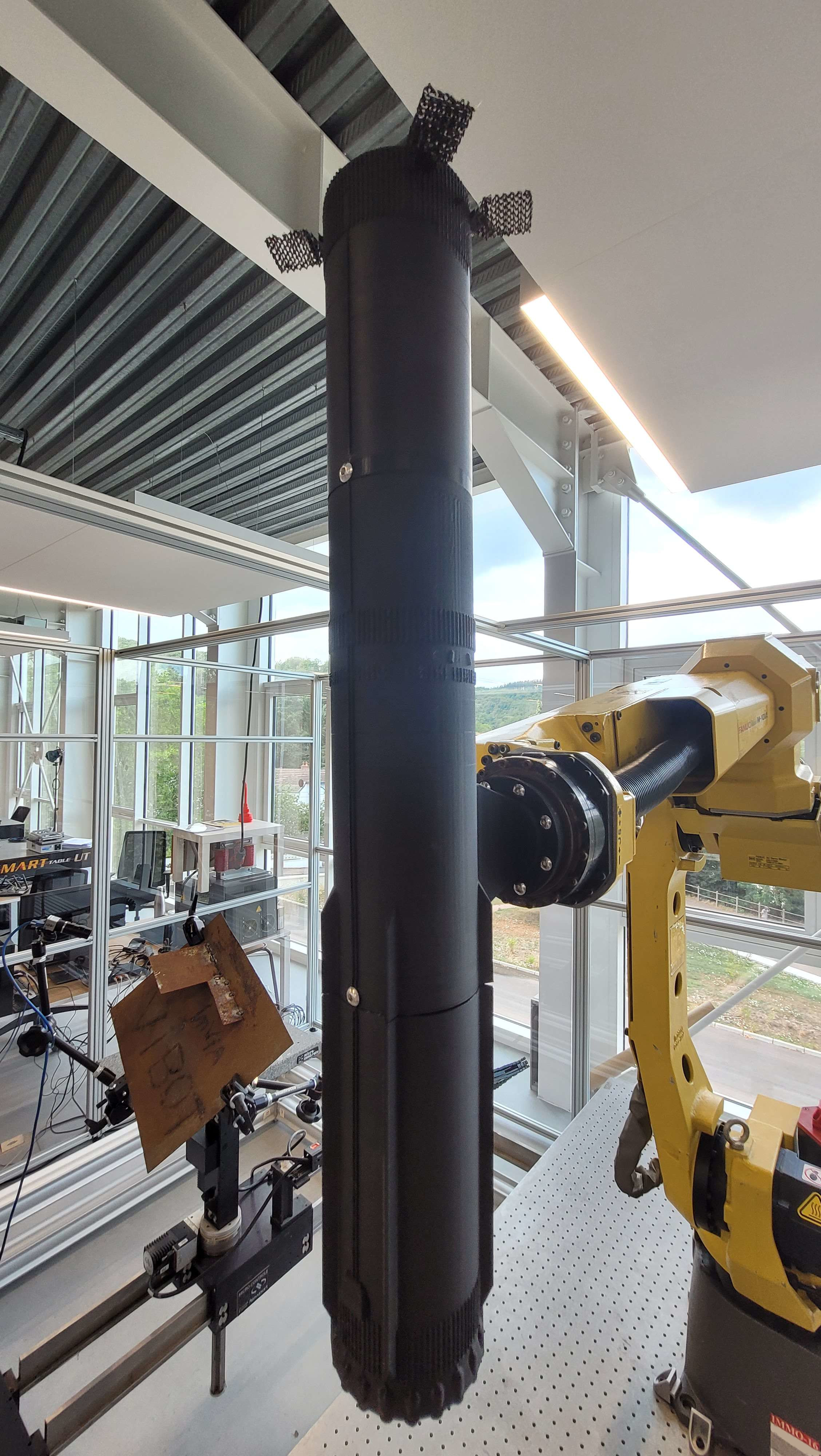
Un projet d'étude est aussi une excuse pour apprendre en pratiquant. Voulant participer aux Olympiades FANUC cette année, j'ai demandé dès la proposition de mon projet d'utiliser un bras FANUC. Pour l'échelle de mon projet, le plus gros robot disponible à l'école m'a été accordé : un M-10iA avec un R-30iA Mate.
L'objectif avec cette cellule robotisée est de recréer le plus fidèlement possible, en flux tendu, l'état de mon environnement de simulation. Une grande précision est nécessaire pour ne pas fausser la lecture des centrales inertielles sur les maquettes.
Dans mon environnement de simulation, mon cycle de contrôle s'exécutera à 50Hz. Je peux donc à la même fréquence relever la position et l'orientation du propulseur, pour l'envoyer au FANUC.
Un début fût d'utiliser la librairie Fanucpy de Agajan Torayev, et le tout fonctionnait très bien après adaptation pour le controlleur R-30iA. J'ai réécrit la librairie Python en C++, et incorporé les contrôle dans mon interface ProxSim. Mais avec la manière que fonctionnait les mouvements, le robot s'arrêtait à chaque point. Evidemment, un objet tombant du ciel ne prend pas de pause...
J'ai donc modifié les drivers-robots écrits en Karel et ai refait un programme TP (nécessaire pour le mouvement) spécifique pour mon utilisation. Voici comment il fonctionne :
A chaque point reçu, le programme Karel calcule la trajectoire qui sera effectuée par le robot par petit bouts. Chaque trajectoire est coupée en ~50 positions intermédiaires sur lesquelles le robot passe en CNT100. La trajectoire est calculée selon une courbe de Bézier entre sa position actuelle et la nouvelle position reçue (sur les 6 composantes du repère WORLD), et met à jour les registres de position.
Pendant ce temps, le programme TP itère sur les registres de positions (1 à 50), et passe à un nouveau groupe de positions (registres de 51 à 100) à chaque fois qu'un point est reçu. Utiliser deux "groupes" de registres permet de ne pas écrire sur un registre en lecture par le programme TP (car concurrence entre le programme Karel et programme TP).
De plus, le controlleur FANUC fait déjà un calcul de trajectoire avec les options CNT qui lisent quelques positions en avance de la position actuelle. Ainsi la position "actuelle" pour mon calcul de trajectoire est en réalité, la prochaine sous-position.
Découper les trajectoires en suite de sous-position me permet aussi d'éviter l'utilisation d'un SKIP CONDITION, qui ralentit obligatoirement le mouvement jusqu'à une vitesse nulle.
Résultats ? Je peux envoyer la trajectoire du propulseur dans ma simulation, point par point, et le robot la reproduit à l'identique, sans appliquer de perturbations superflues sur les capteurs de mes maquettes.
La vidéo présente le robot, recevant des points aléatoires dans un plan, avec des instructions de vitesses aléatoires. Il s'arrête s'il a atteint sa dernière cible, et les mouvements sont parfois saccadés sont causés pas le point de contrôle de la courbe de Bézier : le début de la courbe de Bézier n'est pas encore aligné avec la direction que le robot se déplace, la solution est sur papier, prête à implémentation.
Actuation à distance du robot FANUC
(Vitesse x2)
Conception et fonctionnement des maquettes
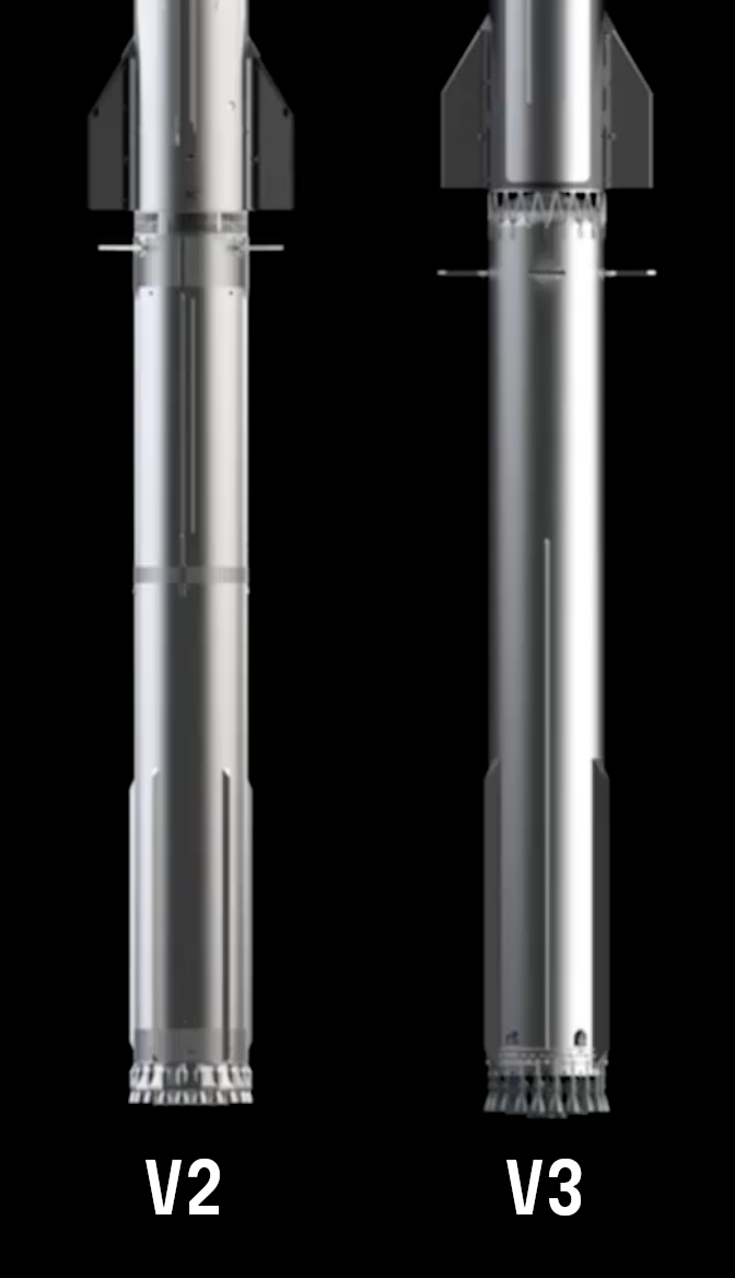
Je dois donc modéliser puis imprimer en plastique un propulseur et une tour, fidèlement au vrai modèles, à l'échelle ~1:144. Ce choix d'échelle assure d'avoir un bon visuel sur la dernière manoeuvre dans la cellule robotisée.
Ce fut mon premier projet de modélisation 3D, et ma première occasion d'utiliser une imprimante 3D.
En utilisant différentes informations officielles de SpaceX et des centaines de clichés de journalistes/reporters, je modèlise le propulseur sur Autodesk Fusion.
Le vrai propulseur fait 69 mètres de hauteur pour 9 mètres de diamètres, ma maquette fait donc 50 centimètres de haut, assez large pour contenir une breadboard.
Vous pouvez apercevoir ces modélisation dans cet outil de visualisation rudimentaire.
Modélisation propulseur & tour sur Autodesk Fusion (Avril 2025)
Maquette Super Heavy
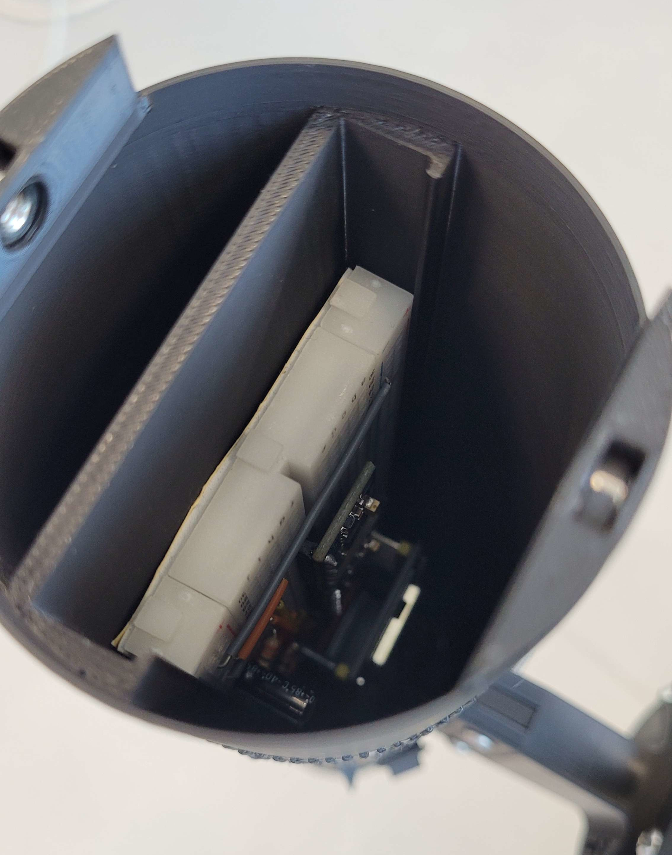
Intérieur de la maquette
La maquette de Super Heavy comporte une batterie 15V et alimente une ESP32 (carte logique programmable, avec communications sans-fils) ainsi que deux centrales inertielles MPU-6050.
Pour faire rentrer le propulseur dans mon imprimante 3D, je le découpe en 3 morceaux :
- La partie haute actionnera les grilles aérodynamiques, mais est vide pour l'instant
- La partie centrale, contient les cartes logiques/capteurs
- La partie basse, où repose la batterie
Le tout s'assemble uniquement avec des vis, mais se fragilise avec les acrobaties exécutées par le robot FANUC.
La partie centrale proche du centre de gravité possède aussi l'attache pour le monter sur le robot, faite aussi sur mesure.
Contrôle Optimal
Les controlleurs PIDs ne sont pas assez robustes pour mon utilisation, car mon système est loin d'être linéaire, que ça soit en terme de contrôle, ou même les forces externes agissant sur le propulseur. Je décide d'utiliser du contrôle prédictif (Model Predictive Control). Il s'agit de prédire, selon un modèle mathématique du système, son état futur après une suite de commandes. On peut ainsi choisir parmis les commandes, celle qui nous convient (le moins d'erreur).
Or pour trouver cette solution optimale, une descente de gradient ne suffit pas : l'espace n'a aucune garantie d'être convexe. Je m'appuie donc sur le papier de recherche Lossless Convexification de Lars Blackmore. Cet algorithme apporte un espace analogue au premier, qui lui est convexe, et où la solution optimale de l'un est la solution optimale de l'autre, si elle existe. Je devrais commencer mon étude de ces papiers de recherche début octobre.
Cette partie est encore sujet de réflexions.
Description
La robotique étant un domaine très large, j'ai proposé en projet d'étude un sujet d'aérospatiale avec une approche robotique, qui fait intervenir passion, théorie, et pratique.
Mon sujet a été accepté par M.FOFI, mon professeur encadrant, en une vingtaine de minutes.
L'objectif est de reproduire le retour d'un propulseur de fusée, Super Heavy.
Une chose aussi compliquée à expliquer bloquée derrière un écran d'ordinateur est plus que dommage, et empêche de vulgariser la science au grand public, c'est une des raisons de pourquoi je veux reproduire ma simulation à échelle humaine dans une cellule robotisée.
Et enfin, utiliser cette reproduction physique pour mettre en place une simulation "hardware-in-the-loop", très utilisés dans les industries spatiales, pour encore plus de réalisme et robustesse dans ma solution.
Lors du retour, le propulseur :
- Redescend à grand vitesse (jusqu'à 4 fois la vitesse du son)
- Se rallume pour freiner
- Se pose sur les deux bras montés sur la tour de lancement.
Mon étude commence à 40km d'altitude, avant que l'atmosphère ne soit assez importante.
Actuellement, ma principale occupation est de m'assurer que mon projet est faisable, je m'occupe donc de faire fonctionner et coordonner toutes les parties du projet : un proof-of-concept. Je m'appuierais à la précision et aux très fins détails une fois tout cadencé.
Essai n°5 Starship/Super Heavy, par SpaceX
Le propulseur exécute une rentrée atmosphérique et fait une dernière manoeuvre, moteurs allumés, pour se faire attraper
Simulation
J'utilise une technologie de simulation très utilisé aujourd'hui pour la recherche et l'IA, notamment chez Nvidia ou Google : MuJoCo.
ProxSim, logiciel de simulation/contrôle à distance.
Interface en développement
Voici mon environnement de simulation, avec un modèle simpliste de Super Heavy. Je peux sauvegarder la télémétrie, ai implémenté mon contrôleur de vol et une interface pour interagir avec la simulation et avec les autres composants de mon projet (maquettes, cellule robotisée FANUC).
Super Heavy pour l'instant se tient debout en tournant ses moteurs à droite ou à gauche à l'aide de simples calculs, en attendant une théorie plus développée. Cet objectif fût surtout un bon prétexte pour mettre en place une simulation contrôlée, stable et réaliste.
On peux voir au centre de l'écran, l'environnement de simulation avec le propulseur. Et sur le reste de l'écran, une interface me permet de mettre en pause, relancer la simulation, modifier la vue, modifier des paramètres et relever la télémétrie importante.
Je peux aussi depuis cette interface contrôler la cellule robotisée FANUC par réseau, pour avoir sa position ou le faire bouger.
Contrôle de la cellule robotisée
Un projet d'étude est aussi une excuse pour apprendre en pratiquant. Voulant participer aux Olympiades FANUC cette année, j'ai demandé dès la proposition de mon projet d'utiliser un bras FANUC. Pour l'échelle de mon projet, le plus gros robot disponible à l'école m'a été accordé!
L'objectif avec cette cellule robotisée est de recréer le plus fidèlement possible, en temps réel, ma simulation. Une grande précision est nécéssaire pour ne pas fausser la lecture des capteurs montés dans les maquettes.
Je peux donner au robot la position et la vitesse du propulseur à intervalles régulière.
Un début fût d'utiliser la librairie Fanucpy de Agajan Torayev, et le tout fonctionnait très bien après adaptation pour mon robot spécifiquement. Mais le mouvement était saccadé. Evidemment, un objet tombant du ciel ne prend pas de pause...
J'ai donc modifié la librarie spécifiquement pour mon utilisation pour obtenir un mouvement fluide (qui sera bientôt publiée open-source).
Résultats ? Le robot reproduit à l'identique ma simulation.
La vidéo présente le robot, recevant des points aléatoires, avec des instructions de vitesses aléatoires. Il s'arrête s'il a atteint sa dernière cible, et les mouvements sont parfois saccadés à cause d'un petit problème de calcul, réglé sur papier.
Actuation à distance du robot FANUC
(Vitesse x2)
Conception et fonctionnement des maquettes
Je dois donc modéliser puis imprimer en plastique un propulseur et une tour, fidèlement au vrai modèles, à l'échelle ~1:144. Ce choix d'échelle assure d'avoir un bon visuel sur la dernière manoeuvre dans la cellule robotisée.
Ce fut mon premier projet de modélisation 3D, et ma première occasion d'utiliser une imprimante 3D.
En utilisant différentes informations officielles de SpaceX et des centaines de clichés de journalistes/reporters, je modèlise le propulseur sur Autodesk Fusion.
Le vrai propulseur fait 69 mètres de hauteur pour 9 mètres de diamètres, ma maquette fait donc 50 centimètres de haut, assez large pour contenir ma carte logique.
Vous pouvez apercevoir ces modélisation dans cet outil de visualisation rudimentaire.
Modélisation propulseur & tour sur Autodesk Fusion (Avril 2025)
Maquette Super Heavy
Intérieur de la maquette
La maquette de Super Heavy comporte une batterie et alimente une carte logique programmable ainsi que deux capteurs de mouvement.
Pour faire rentrer le propulseur dans mon imprimante 3D, je le découpe en 3 morceaux :
- La partie haute actionnera les grilles aérodynamiques, mais est vide pour l'instant
- La partie centrale, contient les cartes logiques/capteurs
- La partie basse, où repose la batterie
Le tout s'assemble uniquement avec des vis, mais se fragilise avec les acrobaties exécutées par le robot FANUC.
La partie centrale proche du centre de gravité possède aussi l'attache pour le monter sur le robot, faite aussi sur mesure.
Toutes les communications se font sans fil avec mon ordinateur.
Contrôle Optimal
Les controlleurs PIDs (que j'utilise pour garder Super Heavy debout) ne sont pas adaptés pour mon utilisation, car mon système est loin d'être linéaire, que ça soit en terme de contrôle, ou même les forces externes agissant sur le propulseur. Je décide d'utiliser du contrôle prédictif (Model Predictive Control). Il s'agit de prédire, selon un modèle mathématique du système, son état futur après une suite de commandes. On peut ainsi choisir parmis les commandes, celle qui nous convient (le moins d'erreur).
Or pour trouver cette solution optimale, une descente de gradient ne suffit pas : l'espace n'a aucune garantie d'être convexe, autrement dit c'est pas possible. Je m'appuie donc sur le papier de recherche Lossless Convexification de Lars Blackmore. Cet algorithme apporte un espace analogue au premier, qui lui est convexe, et où la solution optimale de l'un est la solution optimale de l'autre, si elle existe. Mon étude de ce papier de recherche devrais débuter début octobre.
Cette partie est encore sujet de réflexions.